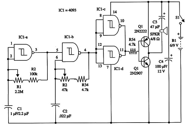
Both Cl and C2 can be altered to change the tone and rate characteristics of the project. You can experiment with several values according the intended application.
The complete schematic diagram of the unit is shown in Fig. 1.

The current drain is about 50 mA. For better audio, the loudspeaker should be installed in a small speaker enclosure.
This circuit can also be used as a Shield for Arduino, PIC or MSP430. You can use pins 1 and 8 for the control.
IC1 - 4093 CMOS integrated circuit
Q1 - 2N2222 general purpose N PN silicon transistor
Q2 - 2N2907 general purpose PN P silicon transistor
SPKR - 4/8 ohm loudspeaker
S1 - SPST switch
B1 - 6 V (four AA cells) or 9 V (battery)
R1 - 2,200,000 ohm potentiometer
R2 - 100,000 ohm, 1/4 W, 5% resistor
R3 - 100,000 ohm potentiometer
R4 - 10,000 ohm, 1/4 W, 5% resistor
R5 - 4,700 ohm, 1/4 W, 5% resistor
C1 - 1 µF to 2.2 µF metal film capacitor
C2 - 0.022 µF metal film or ceramic capacitor
C3 - 47 µF, 12 WVDC electrolytic capacitor
C4 - 100 µF, 12 WVDC electrolytic capacitor


