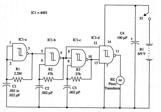
The tones have frequencies of about 1 kHz and 1.8 kHz, but you can easily alter them by changing C2 and C3. Cl determines the alternation rate and can also be varied in a large range of values.
The circuit is powered with four AA cells or a 9 V battery, but it can also function with other voltages in the range between 5 and 12 V.
Only a few milliamperes are drained from the power supply, extending the life of the batteries (if employed).
The complete schematic diagram of the unit is shown in Fig. 1.

R1, R2, and R3 can be replaced by a potentiometer in series with resistors. R1 is replaced by a 2.2 M ohm potentiometer and a 100 k ohm series resistor.
R2 and R3 are replaced by 100 k ohm potentiometers and 10 k ohm series resistors. This way, the device can be used as a simple sound synthesizer.
IC1 - 4093 CMOS integrated circuit
X1 - Piezoelectric transducer or crystal earphone, Radio Shack 27 3-073 or equivalent
S1 - SPST switch
B1 - 6 V (four AA cells) or 9 V (battery)
R1 - 2,200,000 ohm, 1/4 W, 5% resistor
R2 - 47,000 ohm, 1/4 W, 5% resistor
R3 - 27,000 ohm, 1/4 W, 5% resistor
C1 - 0.47 µF ceramic or metal film capacitor
C2 - 0.022 µF ceramic or metal film capacitor
C3 - 0.022 µF ceramic or metal film capacitor
C4 - 100 µF, 12 WVDC electrolytic capacitor


