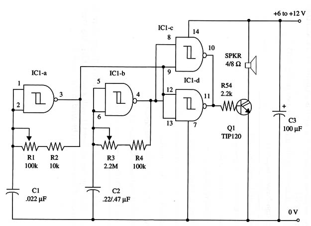
Current drain is about 500 mA, precluding the use of small batteries or AA cells as power supplies. The tone is adjusted by R3, and the rep etition rate by R1.
A schematic diagram of the unit is shown in Fig. 1.

Transistor Q1 must be mounted on a heatsink. To get more power from this circuit, you can replace Q1 with a power FET. Any type with current rated to 2 A or more can be used in this project.
IC1 - 4093 CMOS integrated circuit
Q1 - TIP120 NPN Darlington power transistor
SPKR - 4/8 ohm, 4-inch loudspeaker
R1 - 100,000 ohm potentiometer
R2 - 10,000 ohm, 1/4 W, 5% resistor
R3 - 2,200,000 ohm, 1/4 W, 5% resistor
R4 - 100,000 ohm, 1/4 W, 5% resistor
C1 - 0.022 µF ceramic or metal film capacitor
C2 - 0.22 or 0.47 µF metal film capacitor
C3 - 100 µF, 12 WVDC electrolytic capacitor


