Both frequency and individual oscillator level are controlled by potentiometers in a large range of values. Frequencies can range from 50 to 1,000 Hz with the components listed, and the signal level can be adjusted from 0 V to the power supply voltage.
Connect the output of the generator to the oscilloscope input and see how many waveforms you can generate by varying the eight potentiometers’ positions.
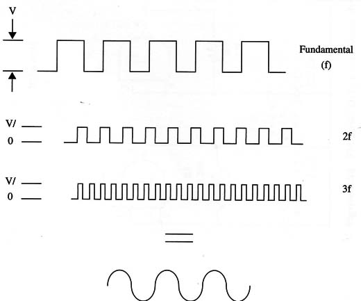
You will see that, if you adjust the first potentiometer to 2 x f (2f), the third to 3 X f (3f), the fourth to 4 x f (4f), and so on, and adjust the output level potentiometers in decreasing steps, you can synthesize a sinewave with good precision. (See Fourier for more details!) See Fig. 1.

If you want to alter the frequency range of this device, you only have to change the capacitors. The circuit can produce signals up to 1 MHz.
The minimum recommended value for C1 to C3 is 120 pF.
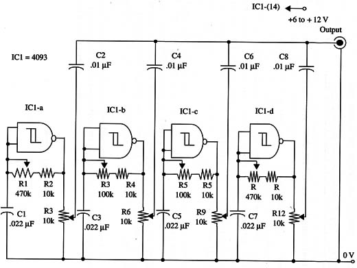
A complete schematic diagram of the Complex-Sound Generator is shown in Fig. 2.

The circuit if powered froma 5 V power supply can be commanded by any microprocessor such as the Arduino, MSP430, PIC etc. acting as a Shield.
IC1 - 4093 CMOS integrated circuit
R1, R4, R7, R10 - 470,000 ohm potentiometers
R2, R5, R8, R11 -10,000 ohm, 1/4 W, 5% resistor
R3, R6, R9, R12 - 10,000 ohm potentiometers
C1, C3, C5, C7 - 0.022 µF - ceramic or metal film capacitors
C2, C4, C6, C8 - 0.01 µF ceramic or metal film capacitors


