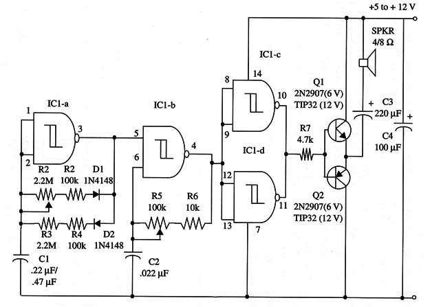
Audio tone duration is adjusted by R2, and the separation between audio pulses is adjusted by R3. The audio tone frequency is adjusted by R5.
The project has a transistorized output stage to drive a loudspeaker with the power depending on the power supply voltage. Outputs up to 4 W can be obtained with a 12 V power supply.
Current drain in this case is up to 1 A. Circuit operation is as explained in other projects using the 4093 in this site.
The output transistors employed will depend on the power supply voltage. For a 5 to 6 V supply voltage, you can use the 2N2222/2N2907 pair of general purpose silicon transistors. But if you’re using a 9 to 12 V supply, you should use the TIP31/TIP32 pair of power silicon transistors, mounted on heatsinks.
Figure 1 shows the schematic diagram of this project.

The duty cycle can be adjusted in a range between 5 and 95%.
IC1 - 4093 CMOS integrated circuit
Q1 - 2N2222 or TIP31 NPN transistor (see text)
Q2 - 2N2907 or TIP32 PNP transistor (see text)
SPKR - 4/8 ohm, 4-inch loudspeaker
D1, D2 - 1N4148 general purpose silicon diodes
R1, R3 - 2,200,000 ohm, 1/4 W, 5% resistors
R2, R4 - 100,000 ohm, 1/4 W, 5% resistors
R5 - 100,000 ohm potentiometer
R6 - 10,000 ohm, 1/4 W, 5% resistor
R7 - 4,700 ohm, 1/4 W, 5% resistor
C1 - 0.22 µF or 0.47 µF ceramic or metal film capacitor
C2 - 0.022 µF ceramic or metal film capacitor
C3 - 220 µF, 16 µF WVDC electrolytic capacitor
C4 - 100 µF, 16 WVDC electrolytic capacitor


