The circuit shown in Fig. 1 produces a strong white noise signal covering a frequency band between a few hertz and more than 100 kHz. Adaptations can change the dynamic range for pink noise generation.
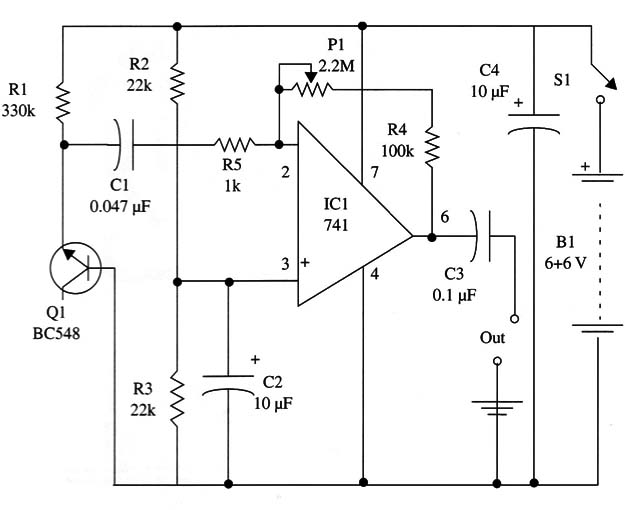
The operating principle is the same as other white noise generatir described in this site: a silicon diode or the junction base-emitter of a silicon transistor is used as the noise source.
In this circuit, the white noise signal is amplified by an operational amplifier IC 741 (NE741, LM741, µA74l, or any equivalent). You can also try using J FET operational amplifiers such as the CA3140, TL070, TL080, or others.
The negative feedback, and therefore the gain, is controlled by adjusting the potentiometer P1.
The operational amplifier has a voltage gain of up to 100,000 X, giving an excellent output to drive amplifiers or other audio circuits. The output impedance is low (about 150 Ω), representing a high power gain.
This circuit must be powered from a 12 V source. To eliminate the need of a symmetrical power supply, the bias is given by a voltage divider formed by R2 and R3.
These components are not critical, and values between 10 k ohm and 100 k ohm are suitable for this task.
The power supply is formed by eight AA cells (12 V) or two 9 V batteries wired in series. However, a supply from the ac power line can be used. In this case, the voltage can range from 12 V to 18 V, according to the voltage regulator integrated circuits used in the project.
The suffix of the ICs given in the parts list indicates the output voltage. For instance, the 7812 produces 12 V at its output.
As the current drain is very low at the output, the IC doesn’t need a heatsink.
The battery power supply is preferred to avoid hum.
Assembly
This circuit can be mounted on a small printed circuit board, including the power supply, or for experimental purposes on a solderless board.
All the components, including the power supply (cells or batteries), can be housed in a small plastic box. A metallic box is recommended, as it can act as a shield to avoid hum.
Any transformer with secondary voltages between 12 and 15 V is suitable for power supply powered from the ac line.
Using the Circuit
This circuit is used as in the previous projects. The white noise is applied to the input of tape recorders, amplifiers, or other circuits and used according to the experiments to be performed.
P1 is adjusted to determine the noise amplitude of the produced signal.
Suggestions
Vary the value of R1 in the range between 220 k ohm and 2.2 M ohm to increase the noise level.
R3 and R4 can be varied in the range between 10 ohm and 100 ohm.
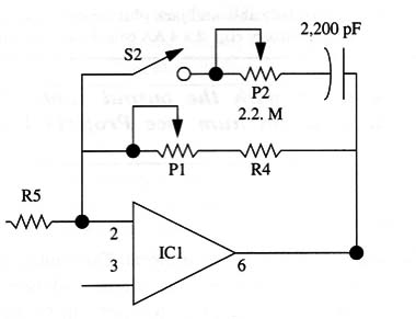
Use a wire between pin 2 and 6 in the network shown in Fig. 2 to add a pink noise option to the circuit. The capacitor can have values between 1,000 pF and 0.47 µF. Closing S1, the circuit will generate pink noise.
Experimenting with White Noise
Some experiments can be performed in addition to the ones described
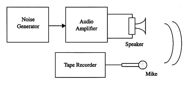
Basic configuration: using an audio amplifier (any of your sound equipment), you can fill an ambient with white noise or pink noise and let your tape recorder record with a microphone to pick the voices. Figure 3 shows how the experiments could be performed. Make sure that the white/pink noise generator is plugged to the auxiliary input (AUX) and that the noise level is adjusted by the amplifier and by the generator (if available).
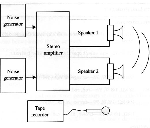
If you are using a stereo amplifier, you can use two noise sources as shown in Fig.4, plugging them to both channel inputs (left and right), or use one input using the amplifier in the MONO option.
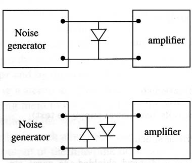
A germanium diode such as the 1N34 can be added to produce a special effect, rectifying the output of the white/pink noise generators signal as shown in Fig. 5.
Semiconductors
Q1 - Any silicon N PN transistor or silicon diode (BC548, 2N3904, 2N 22222)
IC1 - 741 or any equivalent operational amplifier integrated circuit
Resistors
R1 - 330 ohm, 1/8 W, 5% - orange, orange, yellow
R2, R3 - 22 k ohm, 1/8 W, 5% - red, red, orange
R4 - 100 k ohm, 1/8 W, 5% - brown, black, yellow
R5 - 1 k ohm, 1/8 W, 5% - brown, black, red
Capacitors
C1 - 0.047 µF, ceramic or metal film
C2, C4 - 10 µF, electrolytic
C3 - 0.1 µF, ceramic or metal film
Miscellaneous
P1 - 2.2 M ohm potentiometer
B1, B2 - 6 or 9V, AA cells, battery, or power supply (see text)
S1 - SPST, toggle or slide switch
Printed circuit board or solderless board, shielded cable, wires, etc.


