Would you like to create different “space” sound effects with a simple device? Sirens, birds, space monsters, and guns can be imitated with the project we describe here.
The combined positions of the four potentiometers and two switches will give you unlimited possibilities for sound creation.
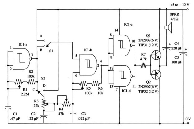
Our circuit is composed of two oscillators: one running at a low frequency between 0.2 and 2 Hz and used as a modulator. The other oscillator runs in the audio frequency range between 100 and 1,000 Hz and is used for tone generation.
The potentiometers are used to control the frequency of the oscillators and also modulation depth. The switches can connect the oscillator in four different ways:
1. In the first position, IC1-b, the audio oscillator is in the free-running mode. Thus, we have a continuous sound, adjusted in frequency by R5. In this connection, S1 is in A, and S2 is in D.
2. In the second mode (S1 in A and S2 in C), the slow oscillator frequency modulates IC1-b, the audio-frequency oscillator. Modulation is adjusted by R1, and depth is adjusted by R3 and R4. The device will generate a continuous sound with variations in frequency.
3. In the third condition, with S1 in B and S2 in A, the device will produce an interrupted sound with a rate given by R1 and a tone by R5. R3 and R4 don’t affect the circuit in this condition.
4. Finally, in the fourth mode, S1 in B and S2 in C, we have an interrupted tone that is modulated in frequency. The interruption rate is given by R1, tone frequency by R5, and modulation depth by R3 and R4.
The capacitors can be altered if you want to create new effects. The capacitors Cl, C2, and C3 can be altered within a wide range of values. Create new sound experiences! A schematic diagram of the soundmachine is shown in Fig.1.

The choice of which transistors to use depends on the power supply voltage. If the power supply is between 5 and 6 V, you should use the 2N2222/2N2907 pair of general purpose silicon transistors.
But if you’re using a 9 to 12 V power supply, you should use the pair TIP31/TIP32 silicon power transistor. These power transistor should be mounted on heatsinks.
The loudspeaker should be mounted in an enclosure for better sound reproduction.
You can also use this circuit as a Arduino Shield, controlling the oscillators by the microcontroller. You only have to power the IC with 5 V and use pins 1, 8 and 13 for control purpose.
IC1 - 4093 CMOS integrated circuit
Q1 - 2N2222 or TIP31 N PN silicon transistor (see text)
Q2 - 2N2907 or TIP32 PN P silicon transistor (see text)
SPKR - 4/8 ohm, 4-inch loudspeaker
S1, S2 - SPDT switches
R1 - 2,200,000 ohm potentiometer
R2 - 100,000 ohm, 1/4 W, 5% resistor
R3 - 22,000 ohm potentiometer
R4 - 47,000 ohm potentiometer
R5 - 100,000 ohm potentiometer
R6 -10,000 ohm, 1/4 W, 5% resistor
C1 - 0.47 µF ceramic or metal film capacitor
C2 - 22 µF, 12 WVDC electrolytic capacitor
C3 - 0.022 µF ceramic or metal film capacitor
C4 - 220 µF, 16 WVDC electrolytic capacitor
C5 - 100 µF, 16 WVDC electrolytic capacitor


