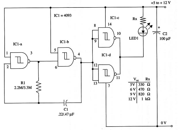
Rx depends on the power-supply voltage according table in the schematic diagram. For more output power, you can use a transistorized output stage as shown in other projects. The powerful output transistor stage using a TIP120 can drive lamps up to 1 A.
A schematic diagram of Led Flasher II is given in Fig. 1.

The flash rate can be altered by changing C1 and R1. R1 could have values between 1 and 10 M ohm, and C2 between 0.22 and 2.2 µF.
Perform experiments to find the value that will give the best performance.
IC1 - 4093 CMOS integrated circuit
LED1 - Red, green, or yellow common LED
R1 - 2,200,000 ohm or 3,300,000 ohm2, 1/4 W, 5% resistor (see text)
Rx - 1/4 W, 5% resistor, according the power-supply voltage (see text)
C10 - 0.22 µF or 0.47 µF ceramic or metal film capacitor
C2 - 100 µF, 16 WVDC electrolytic capacitor


