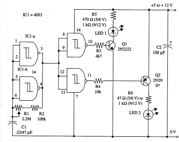
Each transistor driver loads up to 100 mA; thus, you can wire several LEDs to the collectors, each one with the proper series resistor or small incandescent lamp, rated according the power supply voltage employed.
C1 can be altered to change the frequency range. Values between 0.22 and 2.2 µF can be used experimentally. R5 and R6 depends on the supply voltage, and the principal values are given in the schematic diagram.
A schematic diagram of the Complementary-Transistor Dual-LED Flasher is shown in Fig. 1.

You can replace the lamps by hi-power white LEDs with a 47 ohm or 100 ohm series resistor.
The circuit can also be contrlled by microcontrolers such as the Arduino or PIC powering the IC from a 5 V power supply.
IC1 - 4093 CMOS integrated circuit
Q1, Q2 - 2N2222 NPN general purpose silicon transistors
LED1, LED2 - Bicolor or green and red common LEDs, Radio Shack 276-012 or
equivalent
R1 - 2,200,000 ohm potentiometer
R2 - 100,000 ohm, 1/4 W, 5% resistor
R3, R4 - 4,700 ohm, 1/4 W, 5% resistors
R5, R6 - 1/4 W, 5% resistors, values according power-supply voltage (see
schematic diagram)
C1 - 0.22 or 0.47 µF ceramic or metal film capacitor
C2 - 100 µF, 16 WVDC electrolytic capacitor


