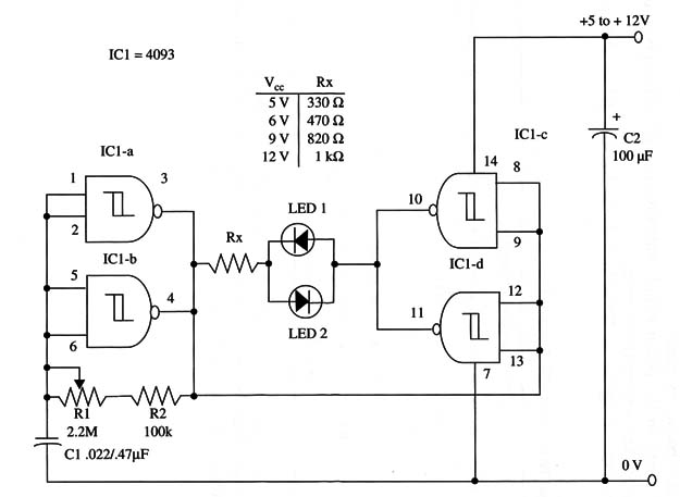
The flash rate is adjusted by R1 and can range from 0.1 to 5 Hz. Values of Cl can be altered in the range between 0.22 and 2.2 µF to change the frequency range.
RX depends on the power-supply voltage, and values are given in a table within the schematic diagram.
A schematic diagram of Two-Color LED Flasher III is shown in Fig. 1.

Proper positioning of the polarized components (LEDs and C2) must be observed. The device can be used as component of alarms or in games, toys, and other applications.
This circuit can be used as a Shield for Arduino, MSP430, PIC and other microcontrollers. You can dictely power it from any output of the microcontroller or use pins of the inputs of any gate of the 4093 IC.
IC1 - 4093 CMOS integrated circuit
LED1, LED2 - Two-color or two common LEDs, Radio Shack 276-012 or equivalent
R1 - 2,200,000 ohm potentiometer
R2 - 100,000 ohm, 1/4 W, 5% resistor
Rx - 1/4 W, 5% resistor (see schematic diagram for values)
C1 - 0.22 or 0.47 µF ceramic or metal film capacitor
C2 - 100 µF, 16 WVDC electrolytic capacitor


