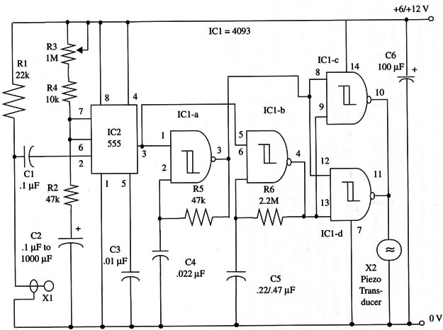
The modulation rate is given by R5 and C4, which control the IC1-a oscillator, and the tone frequency is determined by R6 and C5, which control the IC1-b oscillator. You can vary all these components to change the sound.
IC1-c and IC1-d act as buffers driving the piezoelectric transducer.
You can replace the transducer by a transistorized output stage to drive a loudspeaker if you need more audio volume.
The circuit can be powered from 6 V to 12 V power supplies, and current drain is very low when the tone is off (only a few milliamperes). When the tone is on, the current drain is about 10 mA.
Several pendulum sensors can be wired in parallel to protect locations with many critical points. The sensors can be installed as far as you want from the control circuit.
A schematic diagram of the Timed Pendulum Alarm is shown in Fig. 1.

The sensor is made using a rigid bare wire passing through a bare wire ring, as shown the figure. C2 depends on the desired on period, and it can be in the range of 1 to 1,000 µF. With a 1,000 µF capacitor, the time delay is about 15 minutes (with R3 adjusted to the maximum resistance).
To adjust the device, set R3 to maximum resistance and engage the sensor. After the tone goes off, you can adjust the desired “on” duration.
IC1- 4093 CMOS integrated circuit
IC2 - 555 timer integrated circuit
X1 - Pendulum sensor (see text)
X2- Piezoelectric transducer or crystal earpiece, Radio Shack 273-07 3 or equivalent
R1 - 22,000 ohm, 1/4 W, 5% resistor
R2 - 47,000 ohm, 1/4 W, 5% resistor
R3 - 1,000,000 ohm potentiometer
R4 - 10,000 ohm, 1/4 W, 5% resistor
R5 - 47,000 ohm, 1/4 W, 5% resistor
R6 - 2,200,000 ohm, 1/4 W, 5% resistor
C1 - 0.1 µF ceramic or metal film capacitor
C2 - 1 µF to 1,000 µF, 12 WVDC electrolytic capacitor (see text)
C3 - 0.01 µF ceramic or metal film capacitor
C4 - 0.022 11F ceramic or metal film capacitor
C5 - 0.22 µF to 0.47 11F ceramic or metal film capacitor
C6 - 100 µF, 16 WVDC electrolytic capacitor


