The circuits described until now (BM029E and BM030E) have a duty cycle of 50 percent. This means that the time the LEDs are on is the same for each one.
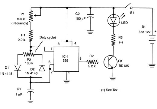
If experiments with only one LED are made, the duty cycle can be changed, and in this case the LED will produce short light pulses or even long pulses with short intervals between them. This can be made using the circuit shown in Figure 1.

This circuit can be used to drive common LEDs, high-power LEDs, or low-voltage lamps with currents up to 500 milliamps.
The transistor must be mounted on a heatsink if the driven current is 100 milliamps or higher. It is recommended that an external power supply is used if the light sources drain more than 100 milliamps. For low-power LEDs, a general-purpose PNP type could replace the transistor, such as the BC558 or others.
R3 depends on the current across the LED. Table bellow gives the values for the resistor according to the LED.
| Resistor values | |
| LED or lamp | R3 |
| Common low-power LED | 1 k X 1/8 W |
| Medium-power LED | 470 ohm. X 1/2 W |
| High-power LED, jumbo | 47 ohm to 220 ohm x1/2 W |
IC-1: 555 integrated circuit timer
Q1: BD136 medium-power NPN silicon transistor
LED: Common or high-power LEDs or lamp
D1, D2: 1N4148 - general-purpose silicon diodes
P1, P2: 100 k ohm potentiometer lin or log
R1, R2: 2.2 k ohm x 1/8 W resistors, red, red, red
R3: See text
C1: 1 µF x 16 V electrolytic capacitor
C2: 100 µF x 12 V electrolytic capacitor
S1: On/off switch
B1: 6 V to 12 V power supply
Other:
PCB, wires, plastic box, etc.


