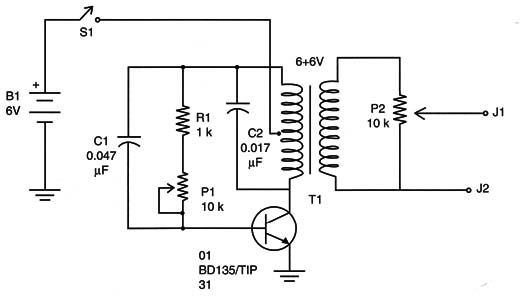
Figure 1 shows the circuit that generates high voltages from common cells.

The circuit is a Hartley oscillator built around the transistor Q1. The frequency is determined by the LC-tuned circuit where L is the secondary of T1 and C is C2.
Cl and R1/P1 form the feedback network that keeps the circuit in oscillation. This network also has some influence on the frequency of the circuit.
P1 can be used to adjust the frequency in a narrow range. This adjustment helps the reader find the point of best performance for the circuit.
The transformer is the same one used in BM028. According to the transformer, it could be necessary to find the best values for (C1 and C2 that provide the highest voltages in the output.
The transistor must be mounted on a heatsink and, since the current drain is high, C and D cells are recommended to serve as the power supply. Do not use transformerless power supplies in this circuit or in any other that has direct contact with living beings (including humans).
The testing and using processes are the same as in the basic project. A neon lamp can be added to indicate the high-voltage generation.
Powering a Fluorescent Lamp
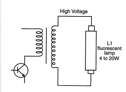
The high-voltage generators used to make experiments with nerves stimulation, can also be used as experimental inverters. A small, common 4- to 8-watt visible or ultraviolet (UV) fluorescent lamp can be powered by the circuits shown here.
Remove the potentiometer from the output and the neon lamp. Then plug the fluorescent lamp to the output, as shown by Figure 2.

Powering on the circuit, in the versions where P1 is present, and adjust this component to the best performance (the highest power).
The UV version can be used to find fluorescence in many different substances, including organic materials, and it can be used to conduct experiments with living beings. How plants, insects, and other animals sense UV light is another interesting bionics experiment.
Using a Derlington Transistor or Power MOSFET
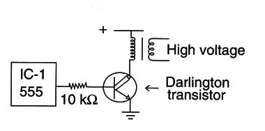
Darlington transistors and power metal-oxide-semiconductor fzeld effect transistors (MOSFETs) can both be used in the basic version of the nerves stimulator. Figure 3 shows how these transistors can be wired to the circuit.

The Darlington transistor types that can be used are the TIP110, 111, 112, 120, 121, and 122.
As for the Power MOSFETS, any type with a drain current of 1 amp and up can be used. With some types, it will be necessary to increase the power supply voltage to 9 volts for the best results.
Collective Shock
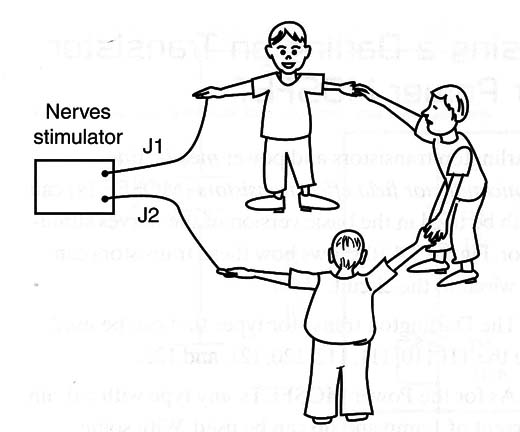
An interesting experiment involving many people can be performed using the nerves stimulator. A group of people would be arranged in a circle With two individuals on one side each holding onto an electrode.
When the group joined hands, they would experience a collective shock, as shown in Figure 4.

When the circle is ready for the experiment, turn on the S1 switch, keeping P2 open.
Some interesting questions can be made after the experiment (or before):
Who experiences the strongest shock: the ones at one side of the circle or everyone? Explain.
Why are all the people affected?
What is a closed circuit?
Why are even those wearing shoes that provide isolation affected by the shock?
Q1: TIP31 (A, B, or C) or BD135 NPN silicon medium-power transistor
T1: Transformer, 6 + 6 V x 100 to 300 mA
P1, P2.: 10 k ohm lin or log potentiometers
R1: 1 k ohm x 1/8 W resistor, brown, black, red
C1: 0.047 µF ceramic or polyester capacitor
C2: 0.1 µF ceramic or polyester capacitor
S1: On/off switch
B1: 6 V or four C or D cells and holder
J1, J2: Output jacks
Other: PCB or solderless board, heatsink for the transistor, knobs
for P1 and P2, plastic boxes, wires, solder, etc.


