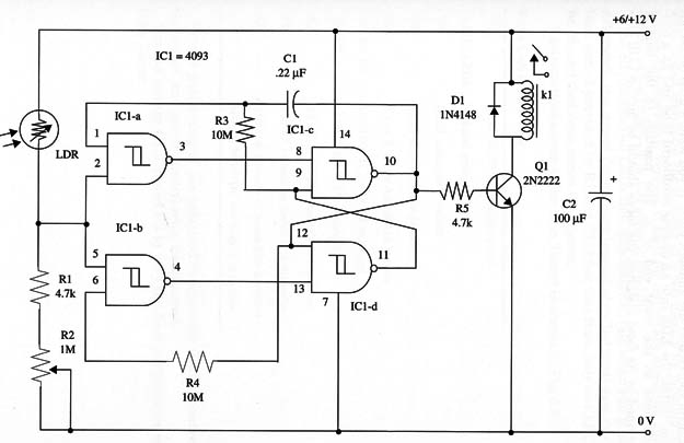
The circuit includes a sensitivity control (R2) and can operate with very weak light sources such as a single match several feet from the sensor. To get greater sensitivity, you can install the sensor (LDR) in an opaque cardboard tube and fix a convergent lens in its front end.
The circuit can be powered from 6 V or 12 V supplies according the relay, and current drain is very low when the relay is off. This is very important if you intend to use the project in battery-powered applications.
A schematic diagram of the Bistable Light Remote Control is shown in Fig. 1.

Use a shielded cable if the sensor is remote from the circuit. The relay is chosen according the power supply voltage (or vice versa), and there are several common types that can be used in this project. Relays with 6 V or 12 V coils draining between 10 and 100 mA can be used. Small appliances can be controlled by a 1 A mini DPDT relay, Radio Shack 275-249.
Proper positioning of the polarized components (diode, electrolytic capacitor, and transistor) must be observed.
Sensitivity is adjusted by R2. Set it according the contrast between the control source and the ambient light. If you want a directional operation, install the LDR into an opaque cardboard tube and fix a convergent lens in the front end of it.
The position of the lens is determined by its focal distance; the focus should be on the LDR surface.
IC1 - 4093 CMOS integrated circuit
Q1 - 2N 2222 N PN general purpose silicon transistor
D1 - 1N4148 general purpose silicon diode
LDR - Cadmium sulfide photocell, Radio Shack 276-1657 or equivalent
K1 - 6 V or 12 V relay (see text)
R1 - 4,700 ohm, 1/4 W, 5% resistor
R2 - 1,000,000 ohm potentiometer
R3, R4 - 10,000,000 ohm, 1/4 W, 5% resistor
R5 - 4,700 ohm, 1/4 W, 5% resistor
C1 - 0.22 µF ceramic or metal film capacitor
C2 - 100 µF, 16 WVDC electrolytic capacitor


