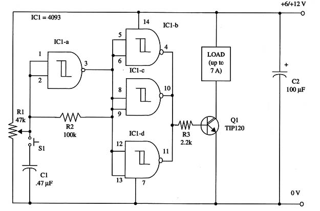
Our experimental Bistable II acts on a relay, closing its contacts when you press S1 the first time and opening the contacts at the second touch.
This circuit can be used to demonstrate the underlying operational principle as used for remote control, alarms, scientific experiments, and many other applications limited only by the reader’s imagination.
S1 can be replaced by a reed switch for alarms and applications in which magnetic fields are used to turn the loads on and off.
Even microcontrollers can be used to control this circuit. O, it can be used as a shield for Arduino, PIC, MSP430 and other microcontrollers.
In this case you only have to a separated 5 V power supply for the IC.
As a load, you can use lamps, small dc motors, and so forth up to 1 A. To drive inductive loads, wire a parallel diode to protect the transistor against high-voltage spikes.
The power supply is chosen to match load requirements. The circuit will operate in the voltage range of 6 V to 12 V without changing any components.
A schematic diagram of the Bistable II is shown in Fig. 1.

To drive loads up to 500 mA, mount transistor QI on a heatsink. You can replace the Darlington transistor with a power FET without any other changes to the circuit.
R1 is adjusted to give a set and reset action by pressing S1. In experimental applications, use an incandescent lamp as the load.
IC1 - 4093 CMOS integrated circuit
Q1 - TIP120 or equivalent Darlington power transistor, NPN
S1 - SPST momentary switch
R1 - 47,000 ohm potentiometer
R2 - 100,000 ohm, 1/4 W, 5% resistor
R3 - 2,200 ohm, 1/4 W, 5% resistor
C1 - 0.47 µF ceramic or metal film capacitor
C2 - 100 µF, 16 WVDC electrolytic capacitor


