You can also use this project as an alarm to detect any strange sounds in your home and to turn on a siren or other annunciator.
The circuit is powered from a 6 V or a 12 V supply according the relay used. When the relay is not energized, current drain is very low.
Sensitivity can be adjusted to a wide range of sound levels by R3 to prevent false operation.
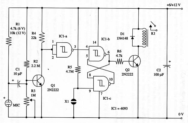
A schematic diagram of the Sonic Relay is given in Fig. 1.

Proper positioning of the polarized components (electret mike, electrolytic capacitors, diode D1, and the transistor) must be observed.
For a remote connection to the mike, use a shielded cable. The shield should be connected to the negative power supply line.
The relay’s coil is rated according the power-supply voltage, and contact requirements depend on the load you intend to control. You can IC1 4093 CMOS integrated circuit use a mini DPDT 1 A relay for small loads (Radio Shack 275-249) or a heavy-duty relay such as a mini SPDT 10 A for other loads (Radio Shack 275-248 or equivalent).
To adjust the circuit, close R3 and turn on the power supply. Clap your hands and at the same time open R3 until the relay turns on. To reset the circuit, touch sensor X1.
Q1, Q2 - 2N2222 NPN general purpose silicon transistors
D1 - 1N 4148 general purpose silicon diode
K1 - 6 V or 12 V relay, mini 1 A DPDT 12V, Radio Shack 27 5-249 or equivalent
MIC - Electret mike, Radio Shack 270-090 or equivalent
X1 - Touch sensor, as described in Project 74
R1 - 4,700 ohm (6 V) or 10,000 ohm (12 V), 1/4 W, 5% resistor
R2 - 2,200,000 ohm, 1/4 W, 5% resistor
R3 -1,000,000 ohm potentiometer
R4 - 22,000 ohm, 1/4 W, 5% resistor
R5 - 4,700,000 ohm, 1/4 W, 5% resistor
R6 - 4,700 ohm, 1/4 W, 5% resistor
C1 - 10 µF, 12 WVDC electrolytic capacitor
C2 - 100 µF, 16 WVDC electrolytic capacitor


