Obs. This article was originally published in Portuguese in a Brazilian magazine and then translated into English to be part of my book Mechatronics for the Evil Genius (TAB- 2006)
Ionic motors are used in spacecraft outside the earth's atmosphere because they can deliver enough power to be useful in a vacuum. They are the fastest engines that man can build. The flux of ions released by an ionic motor can accelerate a spacecraft to theoretical speeds up to 80,000 kilometers per second (km/s).
Unfortunately, practical ionic motors are very weak and need many weeks or even years to accelerate a spaceship to high speeds. The thrust of a large ionic motor is not more than a few grams.
NASA is working hard to create powerful ionic motors, but it is a slow process of creation and experimentation. They will need many more years of experimentation to have practical motors with power enough to move a large spacecraft.
Currently, ionic motors are used to change the position of satellites in their orbits and to make small corrections in their trajectories.
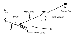
What we propose here is an experimental ionic motor that you can build as a propeller for a miniature spacecraft. You can make a miniature of the Star Trek Enterprise or the Star Wars' pod racer with your operating ionic motor. Figure 1 shows a spacecraft made with a neon lamp that moves in a circular trajectory and is thrust by a flux of ions.
In this project, the evil genius will learn how to mount a high-voltage circuit to create the flux of ions in the engine and how to build the mechanical system for the spacecraft.
Objectives
Certainly, a miniature of a spacecraft with ionic motors that works is a very attractive project for science fairs, as a decoration, or to show the skills of an evil genius in mechatronics. The main objectives for this project are to accomplish the following:
• Show how an ionic motor function.
• Show practical application of the "point effect."
• Make experiments with a very high voltage (VHV).
• Show how Newton's law also works in the space.
Caution! This circuit operates with VHVs. All necessary care should be taken to keep all the parts protected against accidental contact with anyone. It is also important to handle the circuit with care. Do not touch any part when the power circuit is powered on!
Ionic Motors
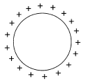
Ionic motors operate according to a phenomenon known for many centuries: the point effect. Electric charges on a body (a solid conductor), because of the long-range action of the electric forces, have the tendency to accumulate on the borders of a conductive body. This is commonly known as the skin effect. If the body is spherical, as shown in Figure 2, the electric charges are distributed uniformly around its surface.
The electric pressure that moves the charges to the borders of the body depends on the density of the charge and on the electrical field. We can say that the electrical pressure is proportional to the square of the charge density. This means that the electrical pressure is nonlinear (if you double the field, the pressure will be multiplied by 4).
Combining the skin effect with the nonlinearity of the pressure, we can explain why the electric field is higher in sharp regions of a solid conductor, resulting in what we call the point effect. As Figure 3 shows, the charges tend to accumulate in the sharp regions of a conductor.
A related important phenomenon is part of this process and will be important for our application: the breakdown. If the charges in the sharp regions of a body reach a voltage that is high enough, a breakdown occurs. The air becomes conductive, and the charges can be expelled in a fluid that is moving. The science that studies this fluid in movement is called electro fluid dynamics (EHD).

But if the movement of the charges is strong enough to cause collisions in the particles that carry the charge (i.e., in the air), the temperature will rise, the electrons will be lost, and light will be produced. The air around the sharp part of the body becomes a plasma.
According to the nature of gas, the energy level of the electrons is different, and thus a color of light is emitted. Neon produces orange light, and the air is yellow, red, or blue according to the energy level involved in the process.
The charges are transferred to the surrounding air particles and then repelled, providing a force that can be used to move the spaceship. According to Newton's law, the force used to repel the charges results in an equal force in the opposite direction by which the spacecraft is moved (see Figure 4).

Although the power released in the process is very low, the speed generated by this kind of propulsion (by the charge particles) is fantastic: 80,000 kilometers per second!
Of course, when we combine very low power with very high speed, we must also be able to build spacecraft that can withstand years in space and fantastic speeds. A typical ionic spacecraft will need many years to reach the approximately 10,000 km/s (36,000,000 km/h) according to the specialists working to make them ideal to explore other solar systems.
HOW Our Project Works
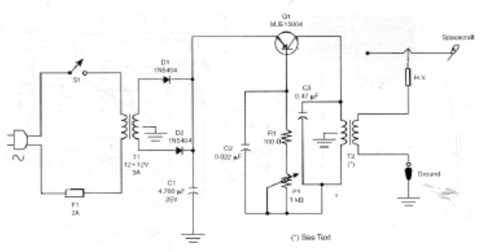
Our basic circuit is made up of a high-power Hartley oscillator and one transistor. This circuit can deliver voltages up to 30 kV, enough to power the spacecraft. In a Hartley oscillator, a coil serves as both the load and the feedback network that keeps the circuit in oscillation (see Figure 5).
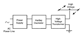
The load in parallel with C3 forms a tuned circuit that, along with the network circuit, determines the oscillation frequency. The circuit can be tuned to a narrow band of frequencies with the use of a potentiometer. This tool allows the user to find the frequency that provides the best performance. The potentiometer actually acts as an accelerator.
The coil used as the load for the oscillator is also the primary coil of the high-voltage transformer. In the original project, we used a flyback transformer found in an old TV. Any flyback can be used. You simply have to take care to find one where part of the core is uncovered. In that part, we have to make the primary coil. Various flybacks can be found at Information Unlimited (www.amazingl.com/transform-ers.htm).
The transistor is a high-power positive-negative-positive (PNP) silicon transistor MJE15004. This transistor can handle the high voltages and currents delivered by the circuit. The power supply consists of a transformer, two diodes, and a filter capacitor. The transformer reduces the power supply line to 12 volts. This voltage is then rectified by D1 and D2 and filtered by C1. The secondary purpose of the transformer is to supply at least 3 amps to support the power delivered from the circuit.
How to Build the Electronic Circuit
Figure 6 shows the schematic diagram for the basic version of the electronic circuit.
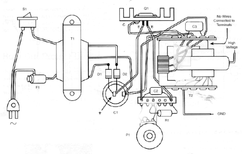
The circuit shown in Figure 7 is simple and uses parts that can be found easily through any dealer. Figure 7 also shows the components assembled and ready to be installed inside a wooden box.
The transistor must be mounted on a heatsink. T2 is a flyback transformer and the flyback must be the type without the tripler circuit that uses diodes and capacitors. This kind of transformer is protected by a plastic cover to avoid any contact with the core. Therefore, it is impossible to add the primary coil required in the project.
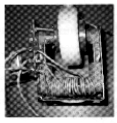
The primary coil is made up of 8 + 8 or 12 + 12 turns of 20 to 26 common plastic-covered wire as shown in Figure 8.
P1 requires a wire-wound potentiometer because the current across the base of the transistor is high. The correct number of turns depends on the flyback. You will need to experiment to find the best value. R1 is a wire-wound resistor.
When testing the circuit, you might alter C2 and C3 to find the best performance. C2 can be a capacitor in the range of 0.01 µF and 0.1, µF, and C3 can be a capacitor in the range of 0.100 µF and 0.560 µF.
All the components fit into a wooden box as shown in Figure 3.4.9. The power transistor is placed on a heatsink, and the transformer is attached firmly in the box with screws. The box used in this project measures 22 X 22 X 15 centimeters. This box, pur-chased in an office supply store, is generally used to file cards.
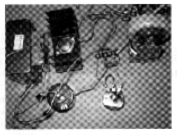
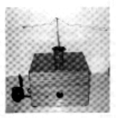
The flyback is also placed inside the box and kept firmly in place with screws. The high-voltage terminal passes through a hole in the cover of the box so that it can provide power to the spaceship. A 2-amp fuse protects the circuit against shorts or other problems.
When mounting, observe the position of the polarized components such as the transistor, diodes, and electrolytic capacitors. Any accidental change in position can burn the component or others in the same circuit. Keep all the wires short in length. Figure 3.4.10 shows the parts placement diagram.
Don't forget the ground wire, a piece of about 3 meters of common wire connected to one of the lateral high-voltage terminals of the flyback. To find the ideal terminal, the reader will need to experiment.
Testing the High-Voltage Circuit
After taking a good look at all the connections, verifying that each one is okay, you can turn on the power switch. A soft noise will reveal that the circuit is oscillating, and a high voltage is being produced.
Place a fluorescent lamp (5 to 40 watts) near the high-voltage terminal and it will glow due to the presence of the high-voltage field. This is a good way to test the circuit.
Parts List—High-Voltage Circuit
Q1 MJE15004 high-power negative-positive-negative (NPN) silicon transistor
D1, D2 1N5404 silicon rectifier diodes
R1 100 Ω x 5-watt wire-wound resistor
P1 1 kΩ wire-wound potentiometer
C1 4,700 µF x 25-volt electrolytic capacitor
C2 0.022 µF polyester film or ceramic capacitor
C3 0.47 µF polyester film or ceramic capacitor
T1 Transformer, with primary coil rated according to the power sup-ply line, and secondary coil rated to 12 + 12-volt x 3-amp center tap (CT)
T2 flyback transformer (see text)
S1 SPST switch (optional ganged to P1)
F1 2-amp fuse with holder
PCB, terminal strips, heatsink, screws, knob for P1, solder, power cord, wires, box, and so on
The Spacecraft
A simpler and lighter-weight spacecraft can be made using a neon lamp, as shown in Figure 11.
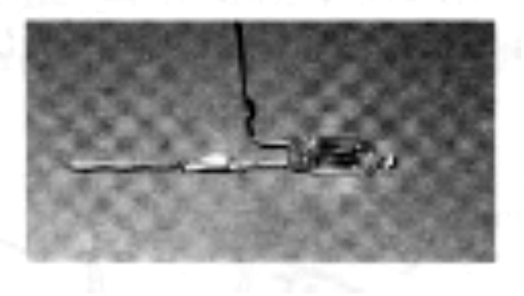
The advantage to using a small neon lamp or a xenon flash lamp is that they both glow when the circuit is powered on and while the spacecraft moves in its circular trajectory.
One terminal of the lamp is soldered to the sup-port and the other to a pin, as shown in the figure. It is very important that each place where solder is used is rounded and without any points. If a point exists in any part of the spaceship, it can cause the leak of ions discussed in the earlier section on the point effect, thus reducing the performance of the motor or even stopping it if the flux is in the opposite direction of the movement.
You can, of course, make other types of spaceships as well. One suggestion is to adapt the system to a miniature of the Star Wars' pod racer, as shown in Figure 12, or of Star Trek's Enterprise.
But remember, the ionic motor is not powerful, and if the miniature pod racer is not light enough, it will move very slowly or not at all. Build your spacecraft to be as light as possible.
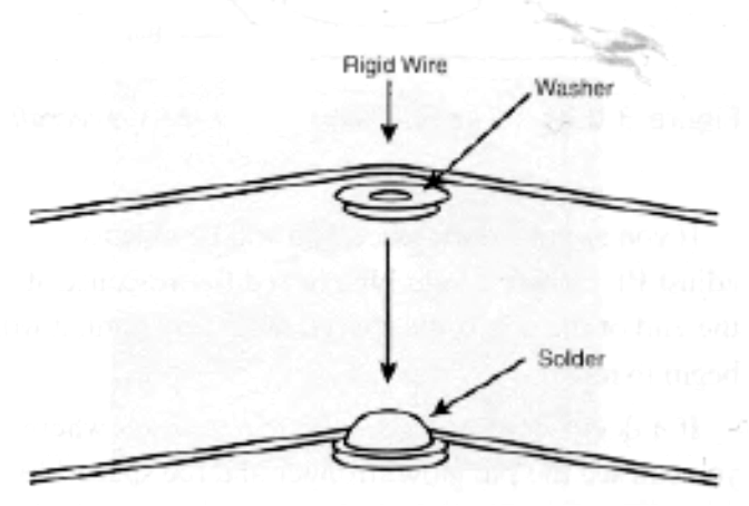
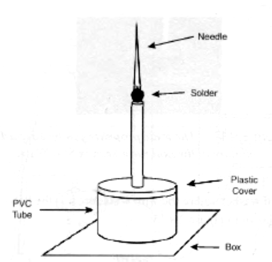
The support on which the spacecraft sits consists of a piece of rigid wire (16 or 14 AWG) 15 to 20 cm long. The wire is supported on a solid base. I used a small washer where the wire is soldered to the base, as shown in Figure 13.
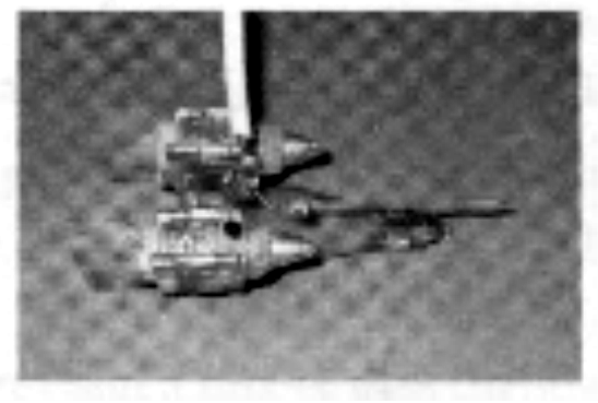
A groove in the spacecraft is made to match the wire support. It is important to verify exactly the point where the groove in the spacecraft should be made. The spacecraft and the support must be perfectly aligned when the spacecraft is released from the support. You can use a small ball of solder on the opposite end of the wire as a balance weight.
Another important point to consider is that no metallic, pointed elements are present in this support. The only pointed element should be the needle in the ionic motor on the actual spacecraft. Figure 14 shows the final support for the spacecraft.
Testing
Place the spacecraft and its support in position. The craft must be free to move in the circular trajectory. Turn on the power. A soft noise will indicate that the circuit is in operation and producing high voltage. The neon lamp in the spaceship (if used) will glow.
If you are in a dark place, you will be able to adjust P1 and see a light blue or red fluorescence at the end of the pin. If the spacecraft is very light, it will begin to move.
If it does not move, adjust P1 to a position where you can see the pin glow stronger, and the spaceship will begin to move. The speed will depend on the weight of the ship and the power released by the high-voltage circuit. If your spacecraft still does not start, you must reduce the weight and/or the friction between the spacecraft and the support. Use a lighter or shorter wire for the support if necessary.
A Space Race
You can organize a competition with your friends to see who can build the fastest spacecraft powered by an ionic motor. Try limiting the length of the support wire to 20 centimeters for all competitors. The competitor whose spacecraft moves in its circular trajectory the most times in 1 minute wins the competition.
Exploring the Project
The high voltage produced by the electronic circuit can be used in many other experiments and applications. High-voltage experiments are very interesting when studying physics at the high school level. The following are some suggested projects.
Wireless Fluorescent Lamp
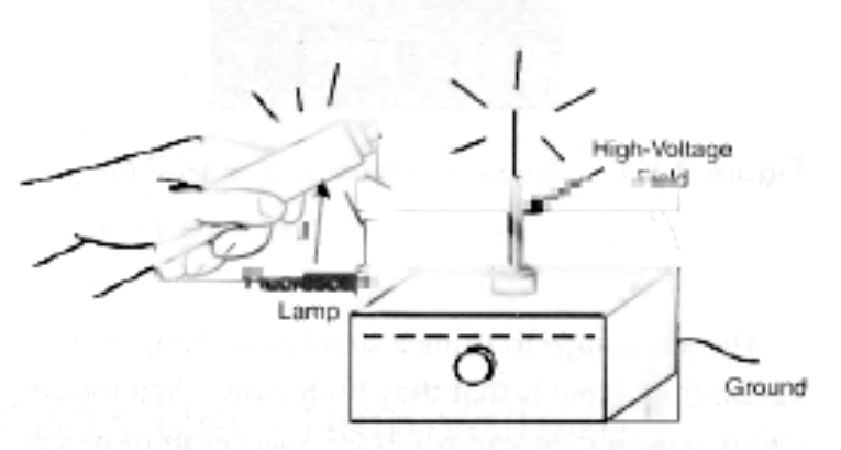
In this exercise, you can become an electronic magician by causing a fluorescent lamp to glow in your hands simply by using the high-voltage electric field produced by the circuit described here. It is recommended to work in a dark place, because the light produced by the lamp is typically not strong enough to be seen in brighter areas.
Take the lamp as shown in Figure 15 and place it near the high-voltage terminal. The lamp will glow.
Caution! Do not touch the high-voltage terminal during the experiment. You will receive a shock. Please remember that although you are working with high voltages (in the range of thou-sands of volts), the discharge is not fatal. Still, the shock can be severe and hurt or burn if you touch any part of the circuit when in operation.
By passing your hands up and down along the sides of the lamp, the lamp will glow only in the parts your hand passes over. You can show that you are able to "control" the electricity in the lamp as if you were a real magician.

