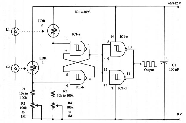
The light input produces a square wave in the output only when the light falling on the sensor is cut in a unilateral mode.
Sensors are light dependent resistors (LDRs) or cadmium sulfide (CdS) photocells (Radio Shack 27 6-1657 or equivalent), and sensitivity can be adjusted to the intended application using R2 and R4. The variable resistors, R1 and R3, should have values appropriate to the light source and the distance from the sensors.
Weak light sources in a dark medium can be detected with large values for all these components. Small values (100 k ohm for the variable resistors and 10 k ohm for the fixed resistor) are used with strong light sources. Output is CMOS compatible, but with an appropriate interface you can drive TTL or other logic families.
A schematic diagram of the Unilateral Counter is shown in Fig. 1.

Short cables should be used to wire the sensors. If you need long wires for the intended application, you probably should use shielded cables. The shield is connected to the circuit positive rail.
C1 is the only polarized component. Position this component properly, as shown in the figure. The power supply is in the range between 6 and 12 V. To prevent false inputs with fast cuts in the light source, you can wire 1,000 pF capacitors between pin 1 and 6 to the 0 V reference.
IC1 - 4093 CMOS integrated circuit
LDR1, LDR2 - LDRs or CdS photocells, Radio Shack 276-1657 or equivalent
R1, R3 10,000 to 100,000 9, 1/4 W, 5% resistors (see text)
R2, R4 100,000 ohm to 1,000,000 ohm potentiometers (see text)
C1 - 100 µF, 16 WVDC electrolytic capacitor
L1, L2 Common lamps, light sources (see text)


