The control is powered from four or six AA cells or, if you prefer, a power supply ranging from 6 to 12 V, depending on the relay coil. Don’t use transformerless power supplies: they are not isolated from the ac power line and can cause severe shocks.
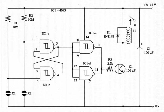
A schematic diagram of the Touch Turn-On/Off Relay is given in Fig.1.

The relay wiring is determined by the type of relay you intend to use. You can use a mini 1 A DPDT (Radio Shack 27 5-249) 12 V, 280 ohm, 43 mA, and wire it as shown in the figure, or use other types of relays according the load requirements. A 10 A SPDT mini relay (Radio Shack 27 5-278) is suitable for heavy-duty appliances.
Of course, the power-supply voltage should be the same as the relay coil voltage.
As a simple rule, you can use 6 or 12 V relays with coil currents ranging from 10 to 100 mA and contacts up to 10 A, or rated according the task you have in mind.
Proper positioning of the polarized components (diode D1, electrolytic capacitor, and the transistor) must be observed. Sensors X1 and X2 are made as we described in other projects in this site.
Don’t use a metallic box to house the device, as there are parts connected directly to the ac power line. Be sure that there is no power line contact with the low-voltage circuit to avoid shocks and dangerous short circuits.
The load is connected as shown for other projects that use relays in an “on” state When the relay coil is energized. However, you can also use the NC (normally closed) contacts to turn off a load when the relay is energized.
Remember that current requirements are high when the relay is en ergized and low When the transistor is off (coil not energized). That is an important factor to consider if you are using batteries to power the unit.
IC1 - 4093 CMOS integrated circuit
Q1 - 2N2222 NPN general purpose silicon transistor
D1 - 1N4148 or equivalent general purpose silicon diode
K1 - 6 V or 12 V mini DPDT or SPST relay (see text), Radio Shack 275-2488
R1, R2 - 10,000,000 ohm, 1/4 W, 5% resistor
R3 - 2,200 ohm, 1/4 W, 5% resistor
C1 - 100 µF, 16 WVDC electrolytic capacitor
X1, X2 - Sensors (see text)


