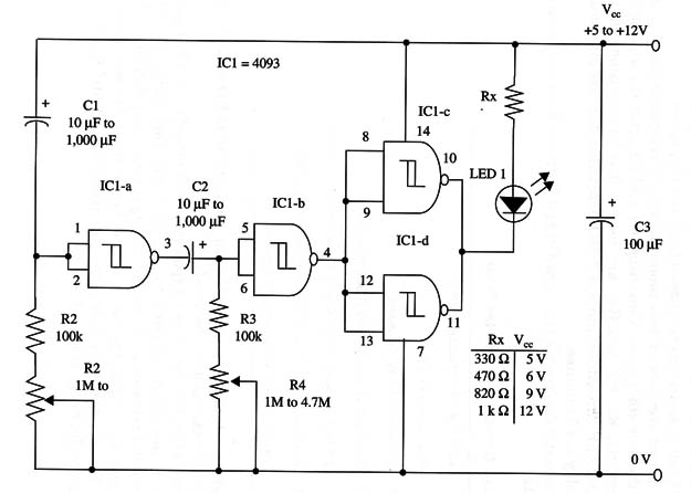
The circuit consists of two monostable multivibrators made with two of the four 4093 gates. Capacitors C1 and C2, with the associated resistors (R1, R2, R3, and R4), are responsible for the time delays.
With 1,000 µF capacitors and a 4.7 MS) potentiometer, the maximum time delay is 45 minutes.
A schematic diagram of the Turn-On and Turn-Off Timer is given in Fig. 1.

Proper positioning of the polarized components (LED and electrolytic capacitors) must be observed.
In use, when the power is on (power switch closed), the LED glows during a time delay adjusted by R2. After this time delay, the LED turns off and remains at this state during a time delay determined by R4 adjustment. After the second time delay, the LED will turn on again. To set a new time delay, open the power switch and wait a few minutes to discharge C1 and C2.
IC1 - 4093 CMOS integrated circuit
LED1 - Red common LED
R1, R3 - 100,000 ohm, 1/4 W, 5% resistors
R2, R4 - 1,000,000 ohm to 4,700,000 ohm potentiometers
R5 - 1/4 W, 5% resistor (see table in the schematic diagram)
C1, C2 - 10 µF to 1,000 µF, 12 WVDC electrolytic capacitors
C3 - 100 µF, 16 WVDC electrolytic capacitor


