Note: this project is part of my book Science Fair and Technology Education Projects published in USA.
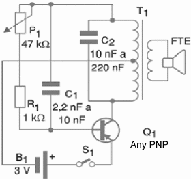
The complete schematic diagram for the Oscillator is given in figure 1.

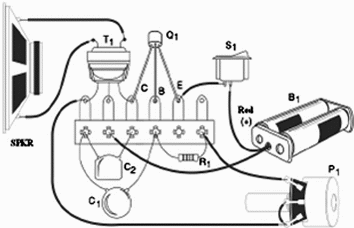
This circuit can be used to test loudspeakers and earphones. Other applications include alarms, signal injector or audio continuity tester. The components can be placed on a terminal strip, considering they are few and not critical, as shown in figure 2.

You can use any general purpose PNP transistor like the 2SA, 2SB, OC, 2N ones or other series. If the circuit doesn’t start, you may change the values of capacitors C1 and C2. These capacitors depend on the specific characteristics of T1 and the transistor.
The transformer can be taken from an old transistor radio or a tape recorder. It is the output transformer and is easily identified because it is connected to the loudspeaker. You can also remove the loudspeaker of the original appliance and use it in this project.
Be careful not to remove the drive transformer of the appliance. It seems like an output transformer, but its characteristics are different from the ones need for this projects and it will not work.
The output frequency can be adjusted by the potentiometer. If the oscillator does not start even when the capacitors are replaced, maybe you have to try another transformer.
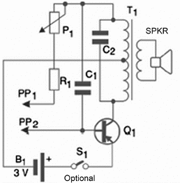
We got good results when using old transistors like the 2SN75, 2SB175, OC74, etc. In order to use the circuit as a continuity tester, the probes are connected as figure 3 shows.

Working With The Project
Your pupils can prepare a work about conductors and isolators, demonstrating with the continuity tester how each one gives different performances to the oscillator.
Ask them to find uses for conductors and isolators, with practical examples in devices and appliances. Based in the timbre of the sound, you can introduce the concept of electrical resistance.
Hartley Oscillator
Q1—Any general purpose PNP transistor (2SA, 2SB, OC, 2N, etc)
B1—2 AA cells with holder
T1—Audio output transformer— 20 to 100 mW—see previous text—1 k ohm primary, 8 ohm secondary
P1—47 k ohm potentiometer
R1—1 k ohm x 1/8 W resistor (brown, black, red)
SPKR—8 ohm small loudspeaker
C1—2.2 nF to 10 nF ceramic or polyester capacitor
C2—10 nF to 220 nF ceramic or polyester capacitor
Other:
Terminal strip or solderless board, base or box, wires, solder, knob for the potentiometer, etc.
Competition:
- Program a competition to separate objects according their electric characteristics: conductors and isolators.
- Make black boxes with resistors having different values. The winner will be the one who finds the lowest resistance box first, using the oscillator as a continuity tester


