Obs. This is one of the large amount of projects I had published in Brazil. This and many others were translated into English and included in my books.
The circuit can be altered to act as an over-temperature relay simply by transposing R1, Q1, and D1 positions with R2 and R3.
To control small loads up to 1 A, a DPDT 1 A mini relay can be used But if you want to control heavy-duty loads such as powerful heaters or fans, a 10 A SPDT mini relay should be used.
Power supply selection depends on the relay used.
Current drain is very low (a few milliamperes) when the relay is off Circuit operation is the same as explained in other projects in this section.
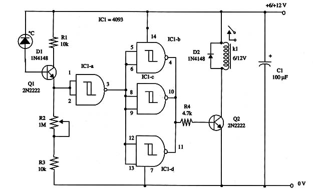
A schematic diagram of the Under-Temperature Relay is shown in Fig.1.

Proper positioning of the polarized components must be observed.
The sensor can be any silicon diode, and it can be placed some distance from the circuit.
To adjust the unit, set R2 to close the contacts of the relay at the desired temperature.
IC1 - 4093 CMOS integrated circuit
Q1 - 2N2222 NPN general purpose silicon transistor
D1, D2 - 1N4148 general purpose silicon diodes
K1 - 6 V or 12 V relay (see text)
R1, R3 - 10,000 Ω, 1/4 W 5% resistor
R2 -1,000,000 Ω - trimmer potentiometer
R4 - 4,700 Ω, 1/4 W, 5% resistor
C1 - 100 µF, 16 WVDC electrolytic capacitor


