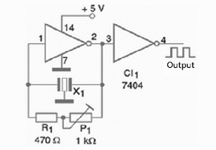
The circuit can also be used as an experimental short wave transmitter. It is very important to remember here that the oscillator uses a TTL integrated circuit, so it can be powered only by a 5 V regulated supply.
Other voltages can damage the integrated circuit. The only adjustment the circuit needs is made by the trimmer potentiometer. It is used to find the point where the oscillation starts. Figure 1 shows the complete diagram of the oscillator.

The components are placed on a printed circuit board (PCB) as shown in figure 1.

The oscillator uses two of the six gates existing inside a 7407 or 74LS04 integrated circuit. The other four inverters can be used in other applications in the same project.
The current drain for the circuit is very low, something around a few tens of milliamperes, and the output consists in a square signal. Placing a small antenna (a wire 40 to 100 cm long) to the output of the circuit makes it able to send signals to a near receiver.
Operating as a low range transmitter it can be used to generate probe signals to receiver adjustments. The signal can be modulated by applying an audio signal to pin 1 of CI-1 by a 1 pF capacitor. The ceramic resonator used in this circuit is a common 10.7 MHz type found in many non-functioning FM receivers.
Testing it is very easy. You can just place a FM or short wave receiver near the oscillator and tune it to its signal.
Challenges and Competitions:
- Use as a telegraph and organize a competition to find out who is the fastest when transmitting a message.
LISTA DE MATERIAS
Semiconductors:
CI-1—7404 or 74LS04—TTL integrated circuit
Resistors:
R1—470 ohm x 1/8 W—yellow, violet, brown
P1—1 k ohm—trimmer potentiometer
Other:
X1—Ceramic Filter = 10.7 MHz
Printed circuit board, 5 V power supply, wires, solder, etc.


