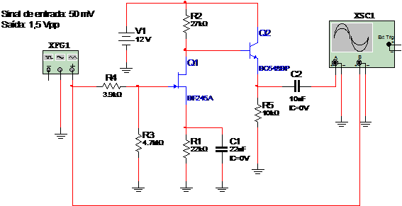
This circuit uses a FET and a BJT to give a x300 gain for the input signal. So a 50 mV signal at the input results in a 1.5 V at the output. Power supply comes from a 12 V source and the output impedance is low. The circuit in the MultiSIM is given in figure 1.

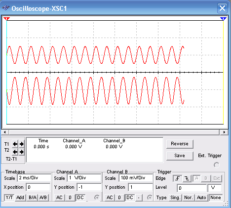
Figure 2 shows the input and the output signal displayed in the virtual oscilloscope of the MultiSIM.

To download the simulation files and Netlist - click here (msb0066.zip)


