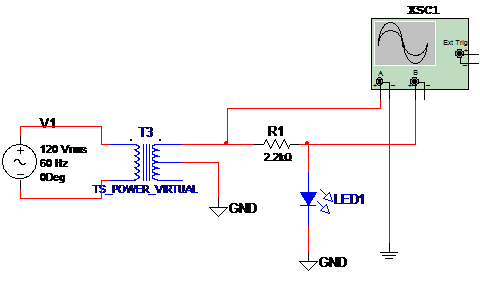
LEDs are diodes and can be tested with a simple configuration that allows the display of its characteristic curve in a oscilloscope. The circuit to make this simulation is given by figure 1. The signal source is a transformer powered from the AC power line. Figure 1 shows the circuit.

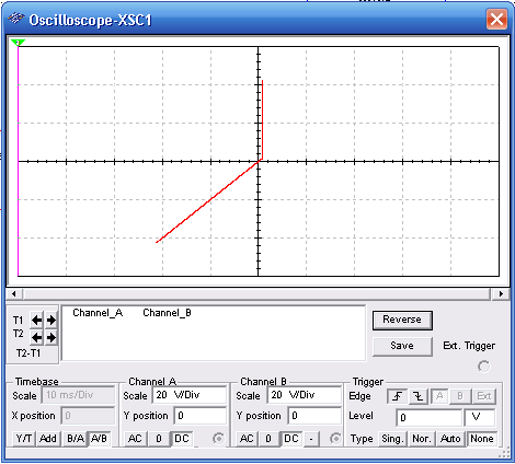
The characteristic curve is observed in the virtual oscilloscope of the MultiSIM as given in figure 2. Observe the time base adjustment A/B.

Download the simulation files and Netlist - click here (msb0079.zip)


