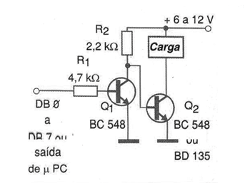
The configuration shown in the figure uses two NPN transistors activating the load when the input goes low (0 V). We can also use a higher power transistor for Q2, thus controlling higher power loads directly. We observed, however, that this configuration is not isolated, like the previous ones. For higher power transistors, the need to use heat sinks should be considered. In this case, the power sector can also be supplied with a voltage other than 5 V.