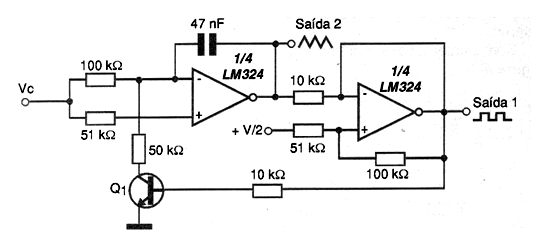
The circuit shown in the figure uses two of the four operational amplifiers found on the LM324 integrated circuit. Most common operational amplifiers can be used in the same configuration, depending on their characteristics only the limit of the generated frequency range. The central frequency of the circuit is given by the capacitor and the transistor used can be any general purpose one like the BC548. The control voltage can vary between 0 and 50 V typically since we have high values of resistors at the input and a limiting circuit. The circuit has two outputs in which triangular and rectangular signals are obtained. The power supply does not need to be symmetrical, but the need for a V / 2 bias voltage (half the supply voltage) at the positive input of the operating second must be observed. This voltage can be obtained with a divider formed by two 10k ohms resistors connected in series.