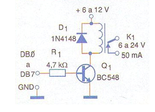
The circuit, shown in the figure, activates a relay when the logic level applied to its input, from the parallel port, is high or 5 V. The use of a high value base resistor ensures that the circuit does not load the output of the door and, more than that, there is a reduction in the voltage obtained. The relay used must be of the sensitive type, with a maximum coil current of 50 mA and contact current according to the application. For the relay, a separate source with a voltage of 6 or 12 V must be used, and the ground of this source is common to the computer ground, GND of the parallel port. The transistor admits equivalent as the 2N2222 as well as the diode D1 which is any one general-purpose type. It is important to note that the connection cable to this circuit must be short, at most 3 meters, so that there are no problems with signal degradation. For the use of all 8 parallel port outputs, 8 circuits like this can be mounted on a single board, having the power supply in common.