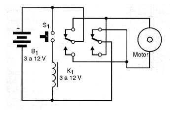
The circuit shown in the figure reverses the direction of rotation of a motor while switch S1 is pressed. Note that S1 can be either a pressure switch or a sensor of any type (reed-switch, limit switch, touch sensor, etc.). The relay used must have the same voltage used to supply the motor in this circuit, but nothing prevents the relay from being powered by an external control circuit. If it is necessary to use a capacitor to dampen the transients due to the switching of the motor, it must be connected in parallel with the supply. This circuit can be combined with others shown in this article to obtain a more complex system behavior. The circuit can be used as the shield coming from the relay command through the output of a microcontroller.