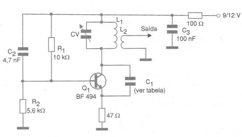
The configuration shown in the figure is one of the most traditional when it is desired to produce signals in the range from 30 MHz to 800 MHz. The maximum frequency that can be obtained from this circuit depends only on the used transistor and the coil. The supply can be done with voltages from 6 V and the consumption of the oscillating step is quite low. The capacitors used must all be ceramic. Capacitor C1, which provides feedback to maintain oscillations, depends on the frequency. Thus, in the following table we give the characteristics of this component and the coil for different frequency ranges.
Frequency Range (MHz) L1 / L2 C1
30 - 50 10 turns / 4 turns 12 pF
50 - 80 7 turns / 3 turns 6.8 pF
80 - 120 4 turns / 2 turns 4.7 pF
120 - 180 2 turns / 1 turn 2.2 pF
180 - 300 1 turn / 1 turn 1 pF
300 - 800 ½ turn / 1/2 turn 0.5 pF
We observed that for the highest frequencies to be reached, the board layout is very important, as any longer track represents additional inductance and capacitance capable of affecting the circuit's operation.
Transistors such as BF254, BF494, BF495 reach up to 200 MHz. In this circuit. For higher frequencies, we suggest using the BF579, BF689K or BF979 which easily reach 800 MHz.