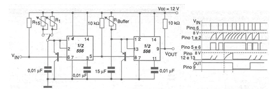
The circuit in the figure alerts you when the frequency of the pulses applied to your input, which are associated with the speed of a motor or mechanism, exceeds a certain value, set in the potentiometers connected to the first timing circuit. The corresponding waveforms are shown in the same figure, observing that the output of the second timer goes to a low level when the input frequency exceeds the set value. In the diagram we represent a double 555 (556) but separate 555 can also be used with equal performance. The intensity of the input pulse (negative pulses) must be capable of triggering the 555. Grounded reed sensors or even common mechanical sensors can be used for this purpose.