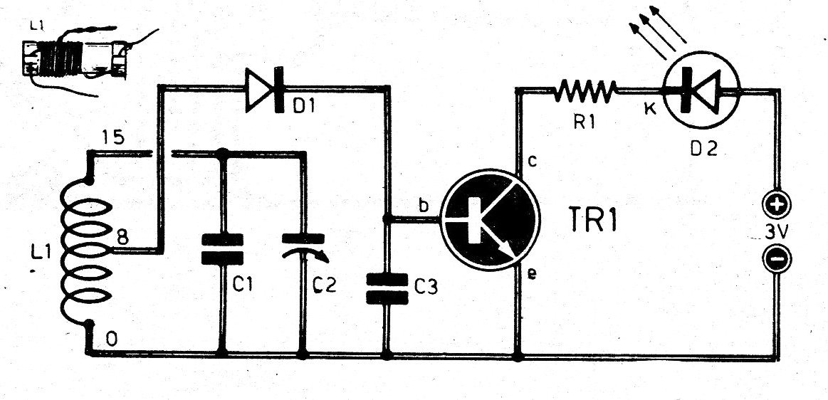
We found this circuit in an old documentation from the 70s. The text is the original one of the time: The word wavemeter is able to tickle the purist ears of some technicians of the new generation, kind of sophisticated, who shiver when they hear "tacky" words practical and earth-to-earth language. With it, you measure the wave emitting the transmitter. The circuit is easy to build. The most difficult point is undoubtedly L1l. With the values of the indicated components, it is possible to tune in 3.5 MHz to 150 MHz, depending on the coil. For 27 MHz, for example, L1 must be wound over an 8 mm shape with 0.5 mm diameter wire, for a total of 15 turns, with a derivation on the eighth turn, turns If the display associated with C2 is calibrated, it is possible to measure the frequency emitted by the transmitter and given, lacking certain, objective information and to the point Power-would be to call this circuit a radio frequency presence indicator. frequencimeter because after all it measures the frequency of the transmitter. But we found it captured by the wave, when close to that. The Led diode will light up and indicate the peak tuning, allowing for a very accurate measurement of the wave frequency.
LIST OF MATERIALS
R1 - 22 ohms
Cl - 10 pF
C2 - 32 pF
C3 - 1,500 pF
D1 -.Any type of germanium diode
D2 - LED diode
TR1 - BC547
L1 - see text