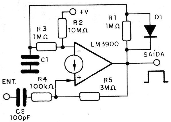
The circuit shown in the figure, generates a positive pulse whose duration depends on C1, from the input pulse. In this circuit, R2 keeps the output low. When the circuit receives the clock, its output goes to high level and resistor R5 locks this condition, feeding back the input (+). At the same time, C1 is charged via R1 until the voltage is reached which, via R3, unlocks the circuit, taking it to its initial state.