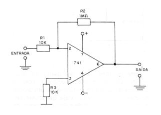
The circuit in the figure can be used in instruments, or other applications where it is desired to amplify a low frequency or direct current signal. The amplifier gain is determined by the R2/R1 ratio, which in this case is 100. The input impedance is determined by the value of R1. If the reader wants to, he can make this circuit gain variable, replacing resistor R2 with a potentiometer of the same value. With the feedback variation between the maximum and corresponding to the 1 M resistance, we will have gain variations between 1 and 100. The source is symmetrical 9 V for this circuit. Remember that in this case the output impedance is of the order of 150 ohms, which means that it is impossible to connect lower impedance loads without the danger of affecting the amplifier's operation (the 741 has an internal short circuit protection).