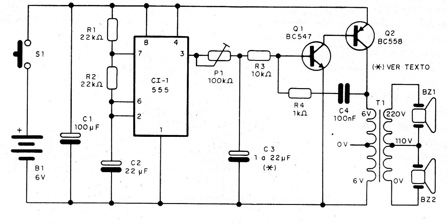
Exciting buzzers we have the circuit of the figure, which has a modulator by interruption, with a 555 and an audio oscillator with two transistors connected to a transformer, to increase the signal voltage and with that the impedance, for greater performance. This circuit generates a single tone interrupted at regular intervals. We can adjust the trimpot P1 so that the average frequency of the sound without the capacitor C3 is the one that gives the greatest performance to the transducer. However, with the addition of C3 we can have a frequency modulation. The depth of the modulation depends on both the value of C3 and the setting of P1. This circuit is of lesser power, being fed with a voltage of 6 V, which can be obtained from 4 small, medium, or large batteries. The primary winding transformer for voltages of 110/220 V and secondary of 6 + 6 V with currents between 100 and 250 mA. Note that two buzzers were connected, but nothing prevents the 110 V winding from being used alone, exciting only one buzzer. The resistors are all 1/8 or 1/4 W and the electrolytic resistors are 6 V or more. The C4 capacitor can have values in the range of 22 to 100 nF and be both ceramic and polyester. For a 12 V supply, we suggest changing Q2 for a TIP32 with heat radiator, but the maximum voltage allowed in the buzzer used must be checked.