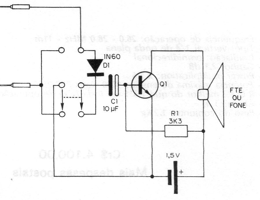
This simple circuit allows the monitoring of both audio and RF signals. With the switch in one position, we have the direct passage of the audio signals to the base of the amplifier transistor (via electrolytic capacitor) and with the switch in the other position, we connect a detector diode to monitor RF signals. The Q1 transistor, which acts as an amplifier, can be of any NPN type for general use, such as the BC547, and the transducer can be either a low impedance headset or a speaker, although the use of headphones high impedance or light output transformer for better results.


