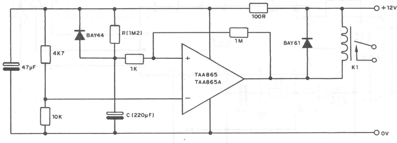
This circuit suggested by Siemens can provide time intervals for triggering values that are given by the expression:
t = C x R
Where:
C is given in farads
R is given in ohms
The electrolytic capacitor used must not have a value greater than 1000 uF, due to the existence of leaks that can impair the functioning of the timer. The resistor R can have its values in the range of 1k to 1.2M. We obtain the following operating characteristics for this timer: Supply voltage (Vs) - 12V (plus or minus 20%).
Maximum time interval - 260 s (approx.)
Repetition time - approx. 12 sec
Switched power - depends on the relay.
A 230 ohms x 12 V relay is required in the original, but any type that has driven currents below 50 mA at 12 V can be used. The BAY44 and BAY61 diodes can eventually be replaced with general-purpose types of silicon.