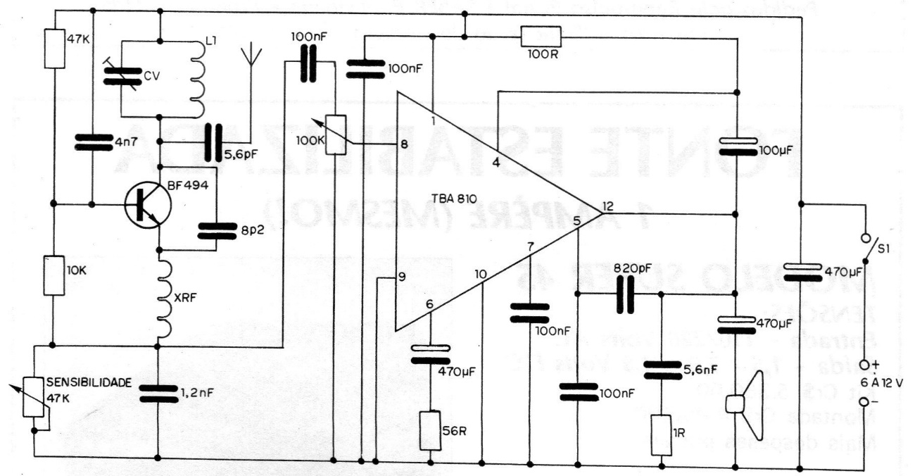
An FM receiver with good sensitivity and with acceptable sound quality in the strongest stations, can be assembled with few components. In the figure we have the circuit of a simple FM receiver that uses only a transistor and an integrated circuit. The receiver consists, basically, of a super-regenerative detector mounted around the BF494 transistor, characterized by its great sensitivity, and of an integrated audio amplifier, which is the TBA810. L1 consists of 5 turns of wire 20 in a shape of 5 mm in diameter without core, while XRF is wound in a resistor of 100 k x num W or in a wooden stick of 2 or 3 mm in diameter. The number of turns, in this case, varies between 40 and 50 and the thread is 32 or thinner. The circuit is supplied with voltages between 6 and 12 V. For the antenna, a metal rod from 40 to 80 cm can be used. Electrolytic capacitors have 12 V or more of working voltage, while the others can be ceramic or polyester. The tuning is done in a small variable for FM or, even, with the help of an adapted trimmer. This adaptation consists of attaching a small axis to the adjustment screw, to which a plastic button will be attached.