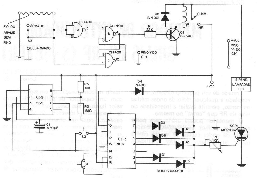
This alarm is designed for doors and windows, but nothing prevents it from being used in cars, entrance gates or protecting backyards. The sensor of this alarm is a very thin wire or wire, which must be well stretched and close or attached to windows and doors that must be protected. The placement of the wire should be such that it will burst when the door or window is forced or opened. When the wire breaks, the input to which it is connected will pass from logic level O to level 1. This will cause a bistable, formed by NAND ports, to change state. This bistable has one of its outputs connected to the base of a transistor, which will then start to conduct, triggering a relay. This relay will feed an astable formed by a CI 555, which controls a 4017 counter. The frequency of this astable is such that we have pulses at intervals of just over 1 minute.
S1 is a pressure switch that must be activated when it is desired to arm the alarm, as it resets the 4017. With the press of this button, the home owner has time to run to the alarm and turn it off. The interval obtained between pressing this button and triggering the alarm is approximately 1 minute. S2 is also a pressure switch that must be pressed to arm the system, but before pressing S1. When pressing this button it will bring the Qo output (pin 3) to the LO level, which means that the next pulse that must be given when breaking the protection wire, will trigger the alarm. S3 is an HH switch that in one position allows the circuit to function normally, and in another it connects the input of the bistable to ground, keeping it in the non-trip condition. P1 allows to adjust the trigger point of the SCR. The relays used are 12V with a current of approximately 100 mA.


