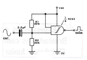
The circuit shown in the figure converts a sinusoidal signal of convenient amplitude into a CMOS compatible rectangular signal. Resistors R1 and R2, typically 22 k, determine the input impedance of the circuit, while C1 must have its value chosen depending on the frequency of the excitation sinusoidal signal. The capacitor must have a low reactance at the chosen frequency. A practical application of this circuit is as a clock for clocks synchronized from the mains. A 60 Hz sinusoidal signal can be converted into a 60 Hz rectangular signal for further division into CMOS stages.