
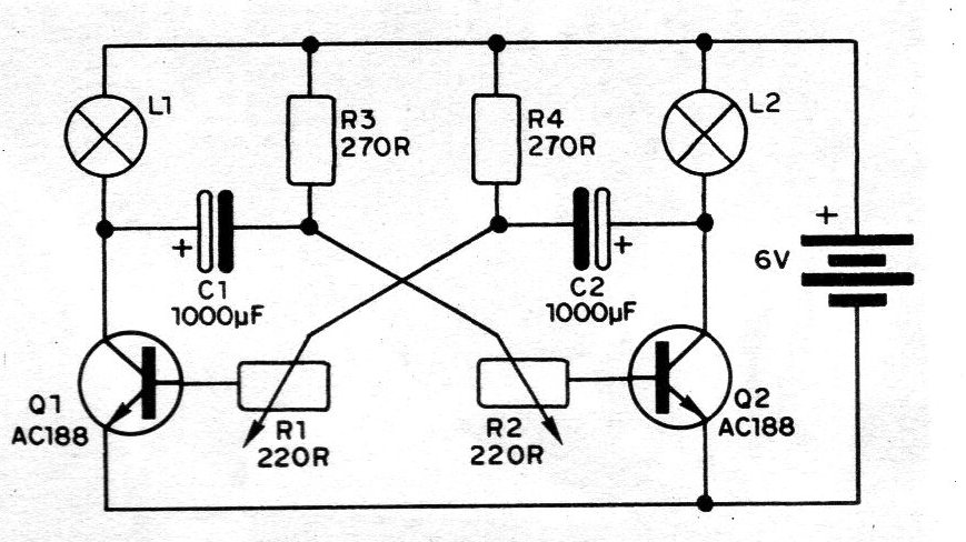
This project is from a 1982 documentation, based on an astable multivibrator with two transistors. The circuit shown in the figure feeds two 6V x 150 mA lamps (GE-1847). The reader can use this circuit in signage, decoration, to obtain special lighting effects in toys, etc. The frequency of the blinks is determined by the values of the electrolytic capacitors C1 and C2 and by the trimpots R1 and R2, where their fine adjustment is made. Resistors R3 and R4 also influence the frequency of operation of your circuit and their values can be between 220 R and 1 k. Originally the author used AC188 transistors in this assembly, but its more modern power equivalents such as the BD136 or BD138, can be used.
| Clique na imagem para ampliar |


