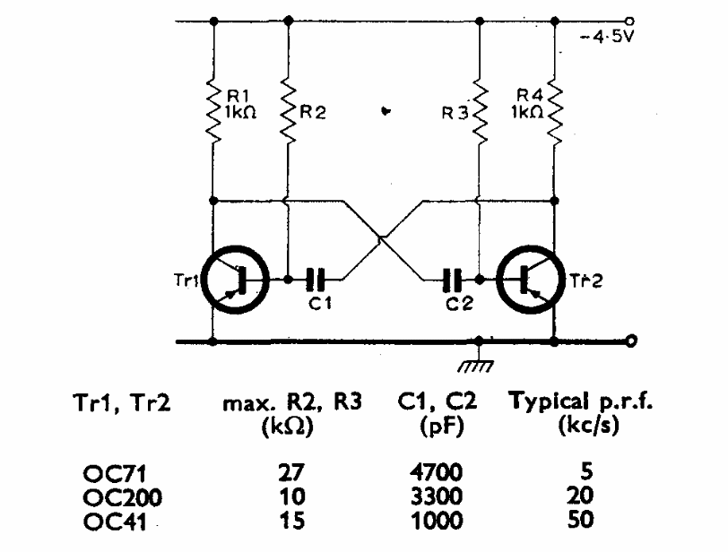
This astable multivibrator was obtained from a Mullard documentation from 1960. The components depend on the used transistor and on the frequency, as shown in the table next to the diagram.
| Clique na imagem para ampliar |

This astable multivibrator was obtained from a Mullard documentation from 1960. The components depend on the used transistor and on the frequency, as shown in the table next to the diagram.


