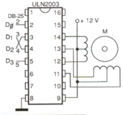
The circuit, illustrated in the figure, consists of the direct application of the ULN2003 in which we have 4 direct inputs to the integrated circuit buffers. In this application, inputs can be obtained from TTL or CMOS digital logic, or directly from the parallel port of a PC. Each winding of the stepper motor is energized when the corresponding input is driven high. Therefore, in the software that will be used, both the activation time of each output and its sequence, or even position for the desired application, must be predicted. Note that there is an independent 12 V supply for the stepper motor, which will operate with a maximum current of 500 mA. In the diagram we have the wire colors with the identification for a conventional stepper motor.