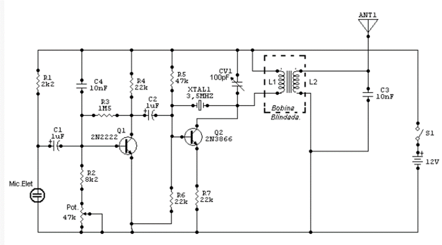
This transmitter was sent by contributing reader Adriano Muniz Moura from Pirapora – MG. It is in 80 meters of the short- wave band (3.5 MHz) and has a fixed oscillator due to the use of the crystal oscillator. Modulation comes from an electret microphone with modulation adjustment made in pot1. CV1 performs fine calibration of the transmitter in addition to adjusting power. The coils are made as follows: L1 is made up of 45 turns of 0.3mm wire on a ferrite core and 6mm in diameter, while L2 is made on L1 with 15 turns of the same wire. If it becomes difficult to adjust the transmitter, reduce the number of L2 turns to 10 turns. The 2N3866 transistor can be replaced for a higher power such as 2SC2078 and must have a good heat sink. The power supply must have a voltage of 12V and a current of approximately 5A. The plate used must be made of fiberglass for greater signal quality and better power adjustment. The resistors are 1/8w and the capacitors are disc-type ceramic except C1 which is electrolytic type. The coil must be fully shielded and grounded to the negative of the source. The equipment can be presented at science fairs as a demonstration of media and even CW training.