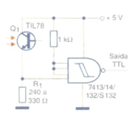
The circuit shown in the figure directly triggers a TTL logic gate, thus requiring a 5 V power supply. Resistor R1 determines the circuit's sensitivity. The output logic level depends on whether the light on the sensor is cut off or an incident on it, remembering that the TTL gate acts as an inverter. Other inverter-trigger functions (Schmitt) can be used in the same configuration.