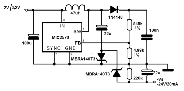
The circuit shown in the figure is suggested by Micrel, based on the MIC2570 boost voltage regulator integrated circuit. This circuit can generate a negative voltage of - 24 V with current up to 5 mA from an input voltage of 1.8 V to 3 V. The inductor is the critical element, being of the 200 uH type and the diode D1 must Be of Schottky type to minimize driving losses. The maximum voltage that can be obtained from this circuit is -32 V. The capacitors must be tantalum and the metal film resistors. Other output voltages can be obtained by programming values of R1 and R2. The formula that allows to calculate the output voltage as a function of these components is:
Vs = 0.22 x (1 + R 2 / R 1)
Applications of this circuit include the powering of liquid crystal displays in portable equipment.


