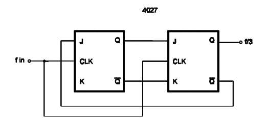
The circuit presented here shows how two flip-flops of a 4027 can be connected to perform a synchronous counter or divide-by-3. If a square wave is applied to the input of this circuit, the output will be a square wave with ’l/ 3 of the input frequency. From the waveforms shown in the figure, the reader can see that the output is not a perfect square wave [50 percent duty cycle]. These states can be decoded by a 4001 as shown in the same figure. The maximum input frequency depends on the power-supply voltage and is 12.5 MHz for 10 V.


