This micro AM radio will tune strong stations in the frequency range between 530 and 1,600 kHz.
The circuit uses only one transistor the amplifier and with a transformer drives a small Ioudspeaker.
As the circuit is very poor in amplification, it needs a Iong wire antenna.
The antenna should be from 15 to 50 feet Iong for best results. A good ground connection is also important.
Of course, this is a small inexpensive transistor radio with low Iistening voIume, particularly on a weak station.
If the station is too weak, replace the SPKR by a Iow-impedance earphone.
The power supply is formed by two or four AA cells and current drain is very Iow, extending their Iife.
The circuit drains only few microamperes.
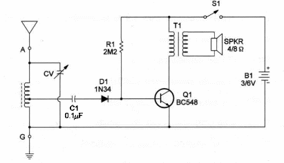
L1 is a tapped Ioopstick, connected to variable capacitor CV.
These items can often be found in non-working transistor radios, as well as the speaker and transformer.
Figure 1 shows the schematic diagram for this project.

Diode D1 acts as a detector and Q1 as an audio amptifien T1 is a common transistor output transformer.
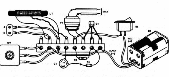
ln Figure 2 we show the components Iayout.

AII the components can be housed in a small plastic box.
A terminal strip is used as chassis in an experimental version.
T1 is a transistor transformer (1,000:8) and the SPKR is a miniature type.
But, if you have an unworking AM radio you can get these parts without spending any money.
To use, close S1 and tune to the desired station by adjusting CV.
You can adjust R1 for the best results according to your transistor gain.
Micro AM Radio
Q1 - BC548 general-purpose NPN transistor
D1 - 1N34 generaI-purpose germanium diode
L1 - Ioopstick - see text
CV - 365 pF variable capacitor
T1 - Transistor transformer 1,000:8
SPKR - 8 Ω x 2 in. miniature spéaker
R1 - 2,200,000 ohm, ¼ W, 5% resistor
C1 - 0.1 µF ceramic or metal film capacitor
S1 - SPST toggle or slide switch
B1 - 3 or 6V - two orfour AA cells
Ideas to Explore
To Iearn more about the circuit or to get better performance:
Replace Q1 with a Darlington transistor, such as a BC517, and find a better value for R1. Values in the range between 2,200,000 and 10,000,000 Ω can be used.
Replace L1 by 20 turns of No. 28 wire on a ferrite rod and try tuning short-wave stations. Use a Iong wire as antenna. Position of the L1 tap must be carefully studied to get best selectivity and sensibility.
Experiment with a crystal earpiece in the place of T1 and SPKR. A 10,000 ohm resistor should be wired in parallel with the earpiece.
Explain how crystal sets or direct-detection receivers operate.
o Define the term “seiectivity".
o What is a galena-crystal?
Science projects:
This receiver can be used to demonstrate how antique radio receivers operated when radio was first invented. It can be presented as a “modern version” of a crystal or galena receiver in a demonstration. An interesting exhibit can be made with this set, the free-power AM receiver (described in this book), and a crystal set.
The circuit can also be used as an RF “sniffer", detecting radio signals produced by experimental circuits in the AM or short-wave band Replace L1 with a 1,000 µH choke and remove C1 to get a sensitive RF sniffer.
Note: This circuit is part of the author’s book Fun Projects for the Experimenter Vol1 – TAB Books – 1998


