
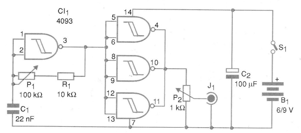
The circuit, shown in the figure, consists of an audio oscillator that generates signals between 100 Hz and 1 kHz approximately when using the selected components values. Capacitor C1 determines this frequency range. For a more sophisticated application, a selector switch can be used to place capacitors from 2.2 nF to 220 nF in three frequency ranges. The signal is rectangular and its amplitude is controlled in P2. This amplitude will vary between 0 V and the voltage used to supply the circuit.
| Clique na imagem para ampliar |


