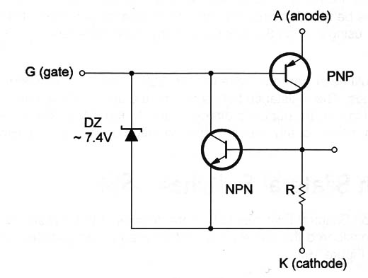
The zener diode determines the triggering voltage, which is normally around 8 V.
But, by connecting a lower-voltage zener between the gate and the cathode it is possible to reduce the triggering voltage.
Symbol
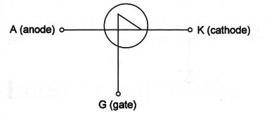
Figure 2 shows the symbol of an SUS.

It looks the same as a common low-power transistor because they use the same bodies.
Specifications
The main specification of an SUS is the triggering voltage or the internal zener voltage. Other specifications are the maximum current and the maximum voltage supported by the device.
Manufacturers identify SUS by part numbers.
Where they are found
Silicon unilateral switches are not common devices today. They can sometimes be found in circuits using SCRs as a trigger element.
The applications using only an SUS as core of any project are rare.
Testing
A multimeter can only reveal if the SUS is shorted between anode and cathode. The resistance between gate and anode is low in one direction and high in the opposite direction due to the PN junction between these two points. Ideally, the test must be made using a special circuit.


